
Encyclopedia
 current location: Home > News > Encyclopedia
 Release time:2026-08-16
 page views:
 If you work in industrial maintenance, you've likely faced this frustrating scenario: a production line running fine one minute, then an unusual noise from the drive end — and upon disassembly, the jaw coupling spider is cracked or shattered, forcing an unplanned shutdown.
Many engineers immediately assume the coupling was undersized and replace it with a larger model, only to see the same failure repeat weeks later. The truth is, spider damage rarely has a single cause. Misalignment, improper axial gap, material mismatch, and environmental factors can all destroy an elastomer long before its expected service life.
This guide walks through the structure, failure modes, diagnostic methods, and optimization strategies for jaw coupling elastomers.
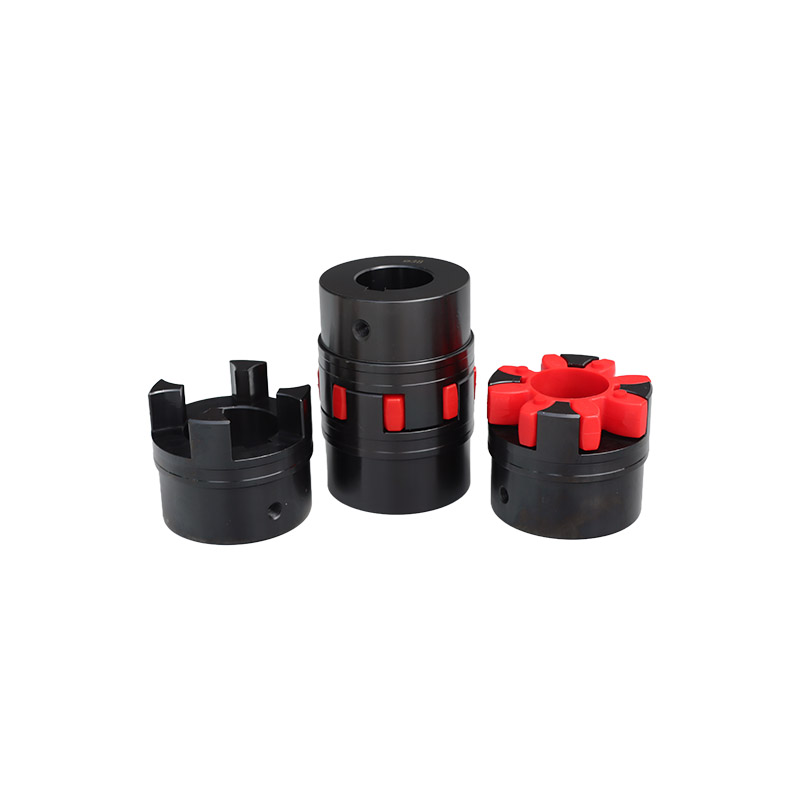
A jaw coupling (also called a spider coupling or Lovejoy-style coupling) consists of two metal hubs with interlocking jaws and a star-shaped elastomeric spider sandwiched between them. Torque flows through hub → spider → hub.
This simple component performs four critical functions:
Key insight: The metal hubs almost never fail. The spider is the designed wear component — the "fuse" of the drive train. Frequent spider failure is a warning signal that something in the system exceeds the design parameters.
A common mistake is sizing the coupling based only on continuous running torque, ignoring startup shock torque and peak load fluctuations. Fans and pumps can generate 2–3 times rated torque during startup; crushers and stamping machines see even greater spikes. Without an adequate service factor, the spider operates under constant high stress and fatigues rapidly.
Sign: Clean shear fracture at the lobe root, especially on equipment with known impact loads.
Excessive radial or angular misalignment forces the spider to undergo uneven compression with every rotation — one side compresses while the opposite side stretches. This cyclic stress causes rapid fatigue and tearing.
Jaw couplings have defined misalignment limits. Typical ML-type couplings allow 0.2–0.5mm radial offset and 1°–1.5° angular deflection. Exceeding these values dramatically shortens spider life.
Sign: Uneven wear — one or two lobes visibly more worn than the rest, often accompanied by increased vibration and elevated bearing temperatures.
The two hubs must be spaced properly to allow the spider to function and to accommodate shaft thermal expansion:
Rule of thumb: The spider should fit snugly between hubs without pre-compression. Refer to the manufacturer's installation sheet for exact values.
Jaw coupling spiders come in three common materials — using the wrong one is a classic reason for failure despite correct sizing:
表格
| Material | Key Properties | Best For | Avoid In |
|---|---|---|---|
| Polyurethane (PU/TPU) | High elasticity, wear-resistant, good strength — the standard choice | General-purpose drives, medium-high speed, normal temperatures | High heat (>80°C), oil/chemical exposure |
| NBR Rubber | Oil-resistant, good damping, wider temperature range | Oily environments, moderate temperatures | High-speed, high-torque applications |
| Nylon (PA) | High strength, heat-resistant, durable | Heavy torque, elevated temperatures | Applications needing high damping or large misalignment |
The most common error: Using standard PU spiders on gearbox outputs where oil splash is present. Oil causes PU to swell, soften, and lose mechanical properties.
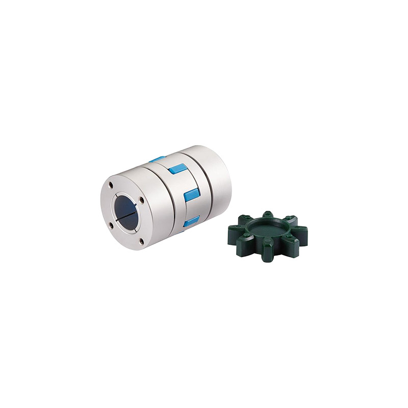
Equipment with frequent direction changes — conveyors, indexing mechanisms, reciprocating drives — subjects the spider to reversed loading with every cycle. The jaws switch from one side of the lobe to the other, creating repeated impact and accelerated fatigue. Spider life in these applications can drop to one-third of normal service life or less.
Every coupling size has a maximum allowable RPM, determined by outer diameter, balance grade, and the spider's heat generation under cyclic deformation.
At excessive speed, centrifugal force expands the spider outward, altering contact with the jaws. High-frequency deformation generates heat faster than it can dissipate, causing the spider to soften — sometimes with visible melting or scorching.
Sign: Melted or blackened, scorched areas on the spider, especially on high-speed equipment.
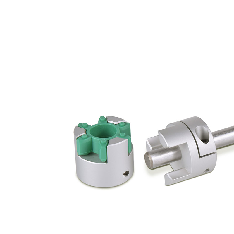
Use this step-by-step process to diagnose spider failures on site:
表格
| Failure Pattern | Likely Cause |
|---|---|
| Even wear across all lobes | Misalignment / chronic light overload |
| One or two lobes severely worn | Radial or angular misalignment |
| Melted / scorched / blackened | Overspeed / high temperature / slippage heat |
| Hardened, brittle, surface cracks | Aging / chemical attack / heat |
| Clean shear at lobe root | Shock overload / undersized coupling |
| Surface scratches, indentations | Installation damage / abrasive dust |
Use a dial indicator or laser alignment tool to measure radial and angular offset. Compare against the coupling datasheet limits. Check for loose base bolts, foundation settlement, and mounting surface flatness.
Verify that the installed spider material matches the environment. Oil exposure with standard PU? High heat with temperature-limited material? Material mismatch will cause failure even when every other parameter is correct.
Address frequent reversing applications. Upsize the coupling for fatigue resistance, reduce reversal acceleration, or evaluate alternative coupling types such as disc couplings.
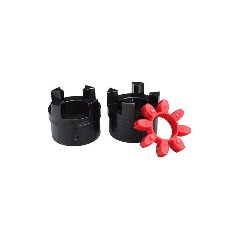
Jaw couplings are versatile but not universal. Consider alternatives in these conditions:
Frequent jaw coupling spider failure is not just a parts problem — it's an alarm signal from the entire drive system. Replacing the spider without identifying the root cause traps you in a break-and-replace cycle.
Remember three principles: correct sizing is the foundation, proper installation is the guarantee, and material matching is the key. Get these right, and spider service life can extend from weeks to years, significantly reducing unplanned downtime.
For non-standard dimensions or special operating conditions, provide complete application data — torque, speed, shaft diameters, mounting space, and environment — to your coupling manufacturer for professional selection support.


Hotline:
+8615066616606 hq@hqcplg.com



 No. 188 Kunlun Road, Hongyun Development Zone, Qingyun County, Dezhou City, Shandong Province